


As automated production lines become increasingly widespread, dimensional inspection is gradually shifting from “spot checks, offline, and manual” to “100% inspection, online, and automated.” Telecentric Measurement Systems are a common type of optical measurement equipment used in such scenarios. By capturing the contour of a workpiece, they enable non-contact dimensional inspection, making them suitable for real-time quality control during high-speed production cycles.

Q1: What is a Telecentric Measurement System?

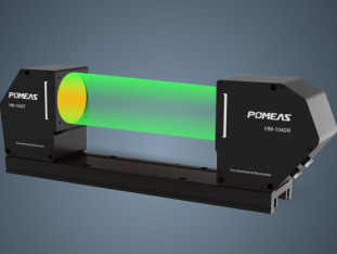
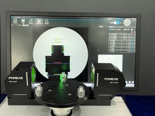
Telecentric Measurement Systems use a telecentric optical system to capture the outline of the object being measured—commonly referred to as a “silhouette.” When light is projected from one side of the workpiece and received on the other, the edges of the workpiece form a clearly defined silhouette image, and the system then calculates dimensions through image processing and specialized algorithms. It is specifically designed for high-speed, non-contact, high-precision dimensional inspection on production lines and can be used for in-line inspection of parameters such as outer diameter, width, clearance, position, and contour.
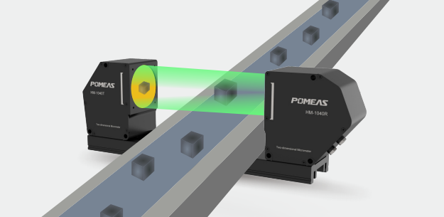
Compared to conventional imaging measurement equipment, Telecentric Measurement Systems place greater emphasis on production line integration, measurement cycle time, and long-term stability. They are typically installed alongside or within production lines to perform real-time measurements on workpieces as they are being transported, and output the results to a host computer, PLC, or sorting mechanism to facilitate automated decision-making and process control.
Q2: What are the features of a Telecentric Measurement System?
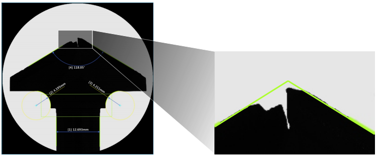
1. High resistance to positional shifts
Telecentric Measurement Systems often employ a dual-telecentric optical system, with both the projection and reception sides featuring telecentric lenses. This design helps minimize the impact of vertical displacement of the workpiece along the optical axis on measurement results, ensuring that clear, sharp contour images can be obtained even with slight variations in the workpiece’s position. Within a certain depth of field—for example, ±20 mm—the device can maintain relatively stable measurement performance. This is particularly valuable in production line scenarios where workpiece fixtures experience slight fluctuations or conveyor belt feed heights are not entirely consistent.
2. Consistent accuracy across the entire field of view
Thanks to the use of low-distortion lenses and specialized algorithms, Telecentric Measurement Systems ensure consistent accuracy across the entire field of view. Users typically do not need to make highly precise adjustments to the workpiece’s position, nor do they need to perform frequent on-site calibrations. For production line inspection, this means that installation, commissioning, and changeover operations can be streamlined, and measurement results remain highly consistent even when the workpiece appears at different positions within the field of view.
3. Suitable for high-speed online inspection
The exposure time of Telecentric Measurement Systems can be as short as 50 μs, enabling them to capture the contours of workpieces in high-speed motion. Shorter exposure times help reduce motion blur, making them suitable for real-time 100% inspection on assembly lines, typically without the need to halt production for measurement. This is particularly important for small parts, continuous feeding, or high-speed conveyance scenarios.
4. A wide variety of measurement tools
This type of equipment typically comes with over a hundred built-in measurement tools. In addition to basic dimensional measurements—such as outer diameter, width, distance, and angle—it also supports geometric dimensioning and tolerancing (GD&T) tasks, contour comparison, and defect distance detection. This wide range of tools means that a single device can meet a variety of inspection needs, reducing the need to repeatedly swap out hardware for different projects and facilitating future expansion of inspection capabilities.
Q3: How do I choose the right Telecentric Measurement System for my needs?


When selecting a model, it is not recommended to focus on a single parameter; instead, you should consider “workpieces, production lines, precision, software, and integration” as a whole. You can systematically identify your requirements by examining the following aspects.
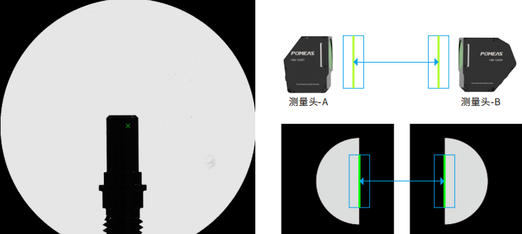
First, identify the measurement subjects and measurement items.
First, confirm the workpiece’s size range, material, surface condition, and edge characteristics, as well as whether the measurement requirements involve outer diameter, width, gap, positional accuracy, contour accuracy, or defect distance. Different workpieces have different requirements for lighting, lens field of view, and algorithmic tools. For transparent, reflective, soft, or easily deformable workpieces, pay special attention to whether the optical solution is suitable.
Second, determine the field of view and measurement range.
The measurement field of view should cover the actual range of position variations of the workpiece on the production line, with some margin built in. If the field of view is too small, even a slight shift in the workpiece’s position may cause it to fall outside the measurement area; if it is too large, it may compromise resolution and increase costs. When selecting a system, a comprehensive assessment should be made based on the maximum workpiece dimensions, position deviations of incoming parts, and the repeatability of the fixture’s positioning.
Third, focus on accuracy, repeatability, and depth of field.
Accuracy must match the product’s tolerances, while also ensuring consistent repeatability. In-line inspection must not only provide “accurate measurements” but also maintain stability during prolonged operation. Depth-of-field parameters are also critical: if there is significant variation in the height of the workpiece, select a model with a depth-of-field range that covers the actual variation to reduce the need for refocusing and installation adjustments.
Fourth, evaluate the production line's takt time and exposure capacity.
The measurement cycle must be synchronized with the production line speed. Understand the equipment’s exposure time, image processing speed, output latency, and triggering method to confirm that it can reliably capture stable images while the workpiece is in motion. For high-speed handling applications, short exposure times and reliable triggering are particularly important.
Fifth, examine the software tools and decision-making logic.
When selecting a system, consider whether the software covers the current measurement tasks, whether it supports functions such as geometric tolerances, contour comparison, and defect distance detection, and whether it allows for easy configuration of acceptance thresholds, output of measurement results, and data saving. The ease of use of the interface, the convenience of switching between models, and the clarity of parameter management also affect daily operational efficiency.
Sixth, verify system integration and communication capabilities.
Online devices typically need to be connected to PLCs, host computers, sorting mechanisms, or MES systems. When selecting a device, verify the supported communication interfaces, input and output signals, trigger methods, and data formats to ensure seamless integration into existing production lines. Installation space, operating distance, cable routing, and protection requirements should also be confirmed in advance.
Seventh, take environmental conditions and maintenance requirements into account.
Production sites may be subject to vibration, dust, oil contamination, temperature fluctuations, or ambient light interference. It is important to understand the equipment’s protective design, installation method, and resistance to interference, and to evaluate the ease of daily cleaning, calibration, and maintenance. Long-term, stable operation is often more important than the performance during a single demonstration.
Eighth, we recommend conducting prototype testing and on-site validation.
Before finalizing the model, conduct tests using actual workpieces whenever possible, covering standard parts, out-of-spec parts, and cases with positional offsets, to evaluate measurement repeatability, cycle time, and decision stability. When conditions permit, simulate the installation spacing and triggering methods used on the production line to verify how well the equipment aligns with existing processes.
Product recommendation


TECHNICAL SOLUTION
MORE+You may also be interested in the following information
FREE CONSULTING SERVICE
Let’s help you to find the right solution for your project!
 ASK POMEAS
 PRICE INQUIRY
 REQUEST DEMO/TEST
 FREE TRIAL UNIT
 ACCURATE SELECTION

- APPICATION CASE
- RESOURCE CENTER
- DOWNLOAD CENTER
SOLUTIONS SUPPORT
- ZOOM LENS SELECTION TOOL
- TELECENTRIC LENS SELECTION TOOL
- FA LENS SELECTION TOOL
- ZOOM RATIO TABLE
- CERTIFIED MODEL
SELECTION TOOL
- WHY POMEAS
- FAQ
- PRIVACY POLICY
- TERMS OF USE
- DELIVERY & RETURN POLICY
CUSTOMER CARE
 ADDRESS
Add.:No.68, Yongwei Road, Baizhoubian, Dongcheng District, Dongguan, China,523000
CONTACT
 Tel:+ 86-0769-2266 0867
 Fax:+ 86-0769-2266 0867
 E-mail:marketing@pomeas.com

Wechat QR code

Software Copyright :2021SR0176001 抄袭必究, 技术支持:誉新源科技