


Inspection tasks in machine vision applications often need to accommodate targets of different sizes or different levels of detail. Frequent fixed-focus lens changes can significantly reduce system efficiency and flexibility. Zoom lenses are the ideal solution to address such needs due to their ability to continuously change the optical magnification without changing the physical lens. Its core value lies in the stepless variation of the field of view range through precise adjustment of the internal optical structure.

I. Optical basis of magnification adjustment
Optical magnification is defined in machine vision as the ratio of the size of the target image on the sensor image plane to the actual target size. For a fixed working distance and image sensor size, the magnification is directly related to the focal length of the lens. The basic relationship can be expressed as:
M ≈ f / WD (Note: more accurate under the approximate condition that the object distance is much larger than the focal length)
Therefore, changing the effective focal length of the system is the central way to adjust the magnification of a zoom lens. Increasing the focal length reduces the field of view and results in higher magnification (smaller area, more detail); decreasing the focal length expands the field of view and results in lower magnification (larger area).
II. The core of the optical structure of the zoom lens: lens group synergistic movement
Achieving continuous changes in focal length and maintaining usable image quality is not accomplished by a single lens shift, but relies on the precise coordinated displacement of multiple sets of optics within the lens. These include at least two key functional lens groups:
1. Zoom group:
(1) Function: This group of lenses assumes the main function of changing the focal length of the system.
(2) Motion: linear movement along the direction of the optical axis of the lens.
(3) Effect: The axial displacement of the zoom group directly and significantly changes the synthetic focal length of the entire optical system, thus realizing the adjustment of magnification.
(4) Core Challenge: Simply moving the zoom group changes the focal length/magnification, but introduces significant image plane displacement. The position of the focal plane for clear images is significantly shifted as the zoom group is moved. If the camera sensor position is fixed, this will cause the image to rapidly go out of focus during the zoom process.
2. Compensation group:
(1) Function: The core role of this group of lenses is to compensate for the displacement of the image plane caused by the movement of the zoom group.
(2) Motion: the same direction along the optical axis, but its displacement trajectory and speed and zoom group there is a specific non-linear function relationship.
(3) Effect: Compensation group according to the position of the zoom group, after accurate calculation of the corresponding displacement, its role is to offset the zoom group caused by the image surface shift, to ensure that in the entire zoom range, the focal plane of the clear image is always stable on the fixed receiving surface of the image sensor. This process is known as maintaining “flush focus” or “image plane stabilization”.
III. Precision realization mechanism of zoom and compensation motion
To ensure that the zoom group and the compensation group (and sometimes other auxiliary lens groups, such as the focusing group or the fixed group) can achieve highly synchronized and precise relative motion in a compact space, industrial grade zoom lenses mainly use the following two well-established mechanical structures:
1. Cam drive structure:
(1) Principle: This is the current preferred solution for high performance industrial zoom lens. The lens group is fixed on a moving slide inside the lens barrel. The inner wall of a finely machined cylindrical cam cylinder is engraved with complex three-dimensional spatial curvilinear grooves (cam grooves). The slider for each lens group is equipped with guide pins that are embedded in the corresponding cam grooves.
(2) Motion transfer: The user rotates the zoom ring on the outside of the lens (or via motor drive) to rotate the cam barrel. The specific three-dimensional contour of the cam slot is designed to accurately convert the rotational motion of the cam cylinder into linear displacement of the lens slider along the optical axis.
(3) Key design: The cam groove profiles corresponding to the zoom group and compensation group have been strictly optically designed and optimized to ensure that the two groups of lenses move strictly in accordance with the preset non-linear relationship during the zoom process (i.e., when the zoom group is moving, the compensation group moves synchronously with the precise compensation movement).
(4) Advantage: High precision of motion transfer, good stability, excellent repeatability and durability, which can effectively support high-quality imaging.
2. Linear guide structure:
(1) Principle: The zoom group and the compensation group are each mounted on separate precision linear guides.
(2) Motion Transfer: A complex link or rack and pinion mechanism is driven by an external knob or motor to force the two sets of lenses to move linearly along their respective guideways.
(3) Motion Control: The design of the linkage or rack and pinion must accurately simulate the required nonlinear displacement relationship between the zoom and compensation groups. relationship.
(4) Applications and Characteristics: This structure may be used in specific designs or in more cost-sensitive applications. The structure is relatively intuitive, but requires a high degree of straightness and guiding accuracy of the guide rails, as well as rigidity and clearance elimination of the drive mechanism to ensure motion accuracy and imaging stability.
IV. Changes in Optical Parameters Accompanying Magnification Adjustment
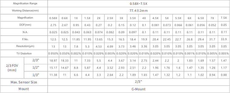
1. Field of view: Magnification is inversely related to the field of view. Increasing magnification significantly reduces the field of view; decreasing magnification increases the field of view. 2.
2. Resolution: With a fixed sensor element size, increasing optical magnification usually means that the system is able to resolve smaller object details (i.e., higher spatial resolution). However, the actual resolution is ultimately limited by the diffraction limits of the optical system and the level of aberration correction. 3.
3. Working Distance: Most zoom lens designs prioritize stabilization of the image plane position (flush focus). However, the position of the object plane (i.e. the optimal working distance) usually changes to some extent with magnification, especially in zoom lenses with a large zoom range. This means that the distance from the lens to the observed object may need to be fine-tuned to restore optimum sharpness after switching magnifications. High-end lenses or well-designed flush-focus lenses can keep this change to a lesser extent.
4. Depth of Field: Depth of field is approximately inversely proportional to the square of the magnification. Therefore, at high magnification, the depth of field will become very shallow, requiring higher focusing accuracy and system stability.
5. Relative illuminance and F-number: During zoom, the position and size of the pupil through which the light passes may change, resulting in a change in the effective F-number of the lens, which in turn affects the luminous flux reaching the sensor (relative illuminance). This may require adjusting the light source intensity or camera exposure time accordingly to maintain consistent image brightness. Modern quality zoom lenses strive to minimize this variation.
Product recommendation
TECHNICAL SOLUTION
MORE+You may also be interested in the following information
FREE CONSULTING SERVICE
Let’s help you to find the right solution for your project!

 ASK POMEAS
  PRICE INQUIRY
  REQUEST DEMO/TEST
  FREE TRIAL UNIT
  ACCURATE SELECTION
 - APPICATION CASE
- RESOURCE CENTER
- DOWNLOAD CENTER
SOLUTIONS SUPPORT
- ZOOM LENS SELECTION TOOL
- TELECENTRIC LENS SELECTION TOOL
- FA LENS SELECTION TOOL
- ZOOM RATIO TABLE
- CERTIFIED MODEL
SELECTION TOOL
- WHY POMEAS
- FAQ
- PRIVACY POLICY
- TERMS OF USE
- DELIVERY & RETURN POLICY
CUSTOMER CARE
 ADDRESS
Add.:No.68, Chongwei Road, Baizhoubian, East district, Dongguan, China, 523000
CONTACT
 Tel:+ 86-0769-2266 0867
 Fax:+ 86-0769-2266 0867
 E-mail:marketing@pomeas.com

Wechat QR code
Software Copyright :2021SR0176001 抄袭必究, 技术支持:誉新源科技