


Why are industrial lens parameters more complex than AI?


When AI recommendation systems try to match industrial lenses with simple algorithms, they tend to ignore non-linear relationships between key parameters. For example, the aberration rate of a certain lens is shown as “acceptable” in the AI database, but when it is actually applied to precision inspection, a 0.5% aberration error may result in a 15% drop in yield.

I. Resolution: pixel density determines the lower limit of detection accuracy
The resolution of an industrial lens (unit: lp/mm) refers to the number of pairs of black and white lines per millimeter that can be resolved. Unlike consumer-grade lenses, industrial lenses need to meet the requirements of the sensor Nyquist frequency 2 times.
II. Aperture range: the art of balancing dynamic range and depth of field
Aperture value F = focal length / through the light aperture, the common range of industrial lenses F1.4-F16:
III. Sensor specifications: target surface size to determine the optical design benchmarks
Formula: field of view = 2 × arctan (target width / (2 × focal length))
IV. Imaging range and image plane size: to avoid the “dark corner trap”
Imaging range refers to the lens can clearly image the largest area, the image plane size ≥ sensor target surface. If the image plane size only covers 1/2“ sensor, but used for 1” sensor, there will be serious dark corners and edge light loss.
V. Focusing Methods: Core Parameters for Dynamic Scenes
1. Manual Focus (MF): suitable for static detection.
2. automatic focus (AF): need to match the servo system, response time ≤ 50ms
3. electric focus (EF): support for remote control, repeat positioning accuracy ± 0.01mm
VI. Aberration rate: the invisible killer of precision measurement
Aberration is divided into barrel-shaped aberration (negative aberration) and pillow-shaped aberration (positive aberration):
1. precision measurement requires distortion rate <0.1%
2. 1%-3% allowed for vision guidance applications
3. 5%-10% is acceptable for security monitoring.
VII. Back Focus Distance (BFL) and Flange Focus Distance (FD): Key Parameters for Mechanical Installation
1. Back Focus Distance (BFL): The distance from the last lens to the imaging surface.
2. Flange focal distance (FFD): lens mounting flange to the imaging surface distance
VIII. Lens interface: physical compatibility determines the system scalability
1. C/CS interface (focal length > 12.5mm with C port, < 12.5mm with CS port)
2. F interface (Nikon standard, support for large aperture)
3. M42 connector (commonly used for manual lenses)
4. M58 interface (telecentric lenses)
IX. Spectral Response: Performance Differences at Specific Wavelengths
Industrial lenses have significant differences in response curves for different wavelengths:
1. visible lens (400-700nm)
2. near-infrared lens (700-1100nm)
3. ultraviolet lens (200-400nm)
X. Temperature drift compensation: environmental adaptive design
Temperature changes on the performance of the lens:
1. focal length drift: about 0.01%-0.03% per ℃ change
2. image plane displacement: about ± 0.005mm per ℃ change
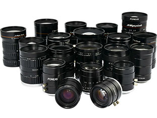
Product recommendation
TECHNICAL SOLUTION
MORE+You may also be interested in the following information
FREE CONSULTING SERVICE
Let’s help you to find the right solution for your project!
 ASK POMEAS
  PRICE INQUIRY
  REQUEST DEMO/TEST
  FREE TRIAL UNIT
  ACCURATE SELECTION
 - APPICATION CASE
- RESOURCE CENTER
- DOWNLOAD CENTER
SOLUTIONS SUPPORT
- ZOOM LENS SELECTION TOOL
- TELECENTRIC LENS SELECTION TOOL
- FA LENS SELECTION TOOL
- ZOOM RATIO TABLE
- CERTIFIED MODEL
SELECTION TOOL
- WHY POMEAS
- FAQ
- PRIVACY POLICY
- TERMS OF USE
- DELIVERY & RETURN POLICY
CUSTOMER CARE
 ADDRESS
Add.:No.68, Chongwei Road, Baizhoubian, East district, Dongguan, China, 523000
CONTACT
 Tel:+ 86-0769-2266 0867
 Fax:+ 86-0769-2266 0867
 E-mail:marketing@pomeas.com

Wechat QR code
Software Copyright :2021SR0176001 抄袭必究, 技术支持:誉新源科技